TTL COMPUTER BY ALESSIO LOMBARDO
[HOME] [WORKLOG]
[HARDWARE]
[CONTACT-ME]
[
![]() ]
]
TTL Computer is a under construction project completely "homemade". The design and the physical construction are curated by Alessio Lombardo, a student of the Industrial Technical Institute - Computer Specialization.
The project is currently divided in two versions:
"Lite" Version: include the "Registers" section, the "ALU" section and the "Control" section.
"Full" Version: include the "Registers" section, the "ALU" section, the Memory (yet to be designed), the Clock and the peripheral.
The project is modular, that is, its parts are divisible and separately modifiable. It is divided in "sections" that is, a group of interconnected Cards. The Sections are connected together with connectors. The cards are simple stripboards of standard size (160x100 or 220x100) except the card "panel" of the "Control" section (in card stock).
Currently, the "Lite" version is complete, and the "Full" version is still in design.
| Section | Card | Size | Lite Version | Full Version | State |
| Registers | Control Unit (RCU) | 160X100 | X | X | Complete |
| Registers A (RRA) | Complete | ||||
| Registers B (RRB) | Complete | ||||
| Data Bus (RDB) | Complete | ||||
| ALU | Core (AC) | 160X100 | X | X | Complete |
| Internal Bus (AIB) | Complete | ||||
| Register (AR) | Complete | ||||
| Control | Board (CB) | 220X100 | X | Complete | |
| Panel (CP) | Complete |
Architecture of TTL Computer Lite
The TTL Computer Lite, as can be seen from the table above, consists of three sections: Registers, ALU, and Control. In this version of the project, the calculations are performed manually with the switches that are located in the Control section.

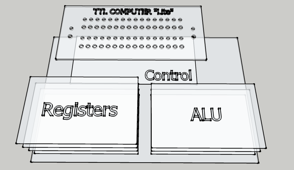
Logic Diagram of Computer TTL Lite and 3D graphical representation
Architecture of TTL Computer Full
Under design...
The "Sections" of TTL Computer